Gauges, tach, switches, warning lights, transponder, fan, seat, harness, and seat brace.
I got the cluster, gauge/switch panel and steering cowl gauges installed this weekend. The gauge panel on the dash has a piano hinge at it’s base so it easily flips down for access to the back of the panel. It has an Air/Fuel meter, fuel pressure gauge, and volt meter on it, and switches for fan, Coolshirt and Coolhelmet, Traqmate power, camera power.
Over the last couple of years I struggled frequently with engine management problems. The A/F meter and fuel pressure gauge were attempts to help understand what was going on. When your car hiccups on the track, the first question that pops into your mind is “fuel or ignition”. And with a fuel pressure gauge right in front of you, some of the possibilities can be excluded immediately. Anyone who’s been there will tell you that being able to reduce the number of causes with certainty is a huge step forward. Well, that is if you pay attention. As it worked out I would have figured out my problems a lot sooner if I’d not taken a year to start believing what the A/F was trying to tell me. Such are the lessons one must learn when they’ve gotten thru life mostly on their good looks.
Both the A/F meter and FP gauge have analog outs that feed to the Traqmate. Or used to, and will again once I get around to installing the TM.
The switch panel has dual grounds going to different locations. Another lesson learned is that high quality grounds make everything happier.
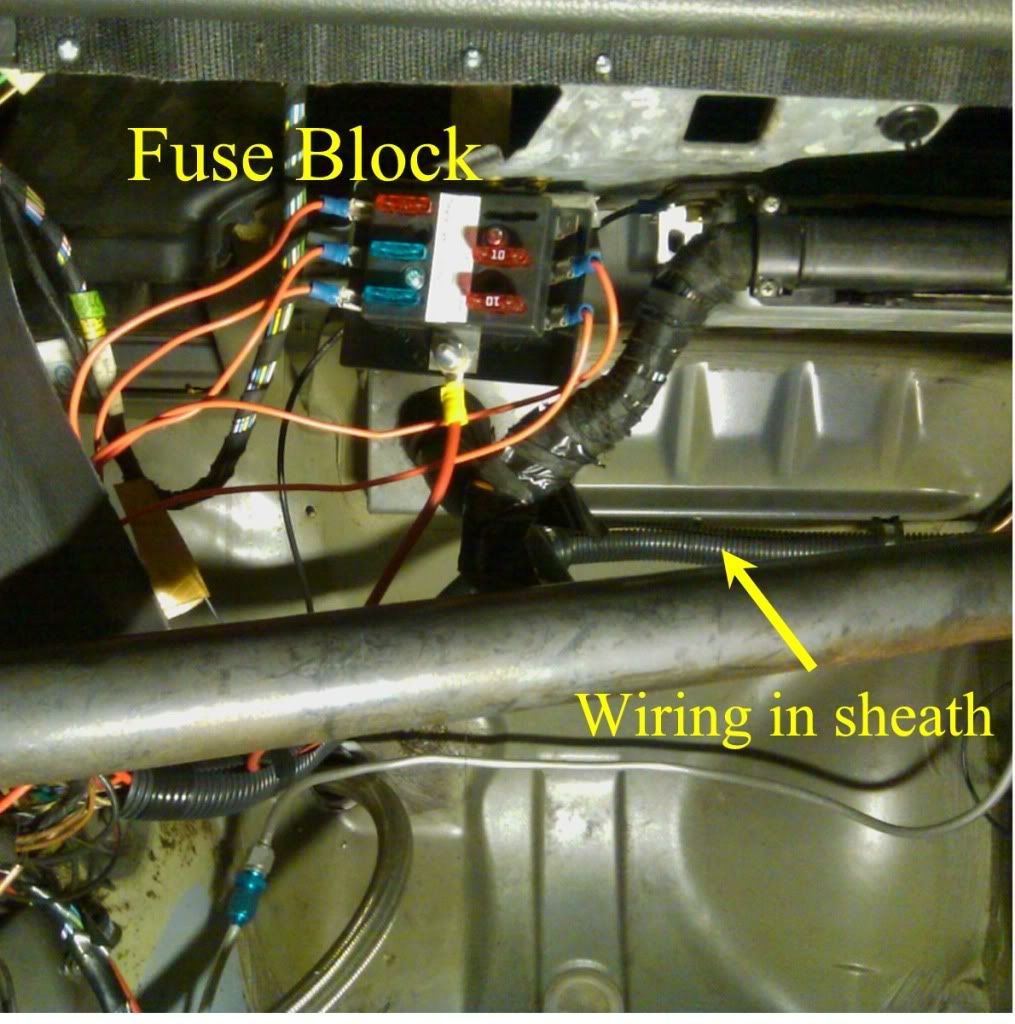
Behind the scenes there’s a 6 position fuse block going to switched 12V so most everything has it’s own fuse. The alternative would be a bunch of inline fuses but that’s a kludge. Here’s a pic of the fuse box from Old#6.
The steering wheel cowl pieces, which includes the mounts for the oil temp, pressure, and coolant temp gauges got installed once I came up with an alternative to the long 5mm screws that the cowl really wanted. I like having the critical gauges right in front of me instead of off to the side because the eyes need to divert less to scan them. Nothing like being on engine 11 to appreciate gauges. If you want to hear more about stepper motor gauges, mechanical guages, and getting data on a Traqmate Data logger read the “Addendum” after the pics. 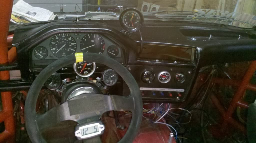
Installing the tach proved to be a little tricky. I should have mounted the tach’s base before I installed the dash. Once I got the dash in tho, I was unwilling to pull the SOB back out without out a helova good reason. I had hoped that screws would be able to get enough purchase in the dash to hold the tach firm, but it turns out there’s a layer of steel in the dash so the screws went in a bit and then just stopped.
There was no way I was going to get a drill in there to get thru the steel because there wasn’t room under the windshield. I decided that this was fate telling me that it was finally time to get one of those 90deg close quarters drills. After a trip to Harbor Freight, the tach went in nicely.
For oil pressure and coolant pressure warning lights I have a bank of LEDs on each side of the dash. Red for oil and amber for coolant. When I was playing with warning lights a couple years ago I found that no matter where I put the warning light I could not rely on instantly seeing it. That motivated me to put warning lights on both sides of the dash so no matter which way I was looking I’d immediately spot loss of pressure.
Most folks don’t have a coolant pressure switch and that’s a mistake. A coolant temp gauge will generally not warn you about a loss of coolant because the first thing that happens with a coolant leak is the coolant drops away from the coolant temp sensor. That makes it an air temp sensor.
When I first set up these warning lights a couple years ago I bought a bunch of different kinds of lights from Radio Shack and ebay. After experimenting with them all to compare brightness and field of view I settled on the banks of LEDs in the pic. They are so bright that if I start the car in darkness I have to close my eyes so the warning lights don’t burn out my retinas.
Here’s a pic of the warning lights from old#6. 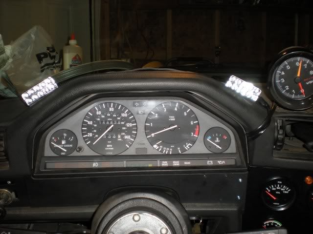
My old transponder went in w/o drama to switched 12V. Even I can’t screw that up.
The saga of the fan and switch. The PO had started the install of a SPA fan so the relay had been in place and a wire run to his old dash. But when I connected the wire that he’d set up for his old dash to my switch, the switch illuminated…WTF?. That shouldn’t have happened. Maybe there was 12V on the wire coming from the fan’s relay, or maybe the pins on that switch were not what I thought. The fan relay had a little diagram on it, but it wasn’t legible with any certainty w/o a microscope. So I spent 15min with jumper wires and a multimeter playing with the relay to figure out exactly how it behaved. Interestingly enough, the relay’s secondary (to the fan) behaves exactly the same no matter if you reverse 12V and ground on the relay’s primary (to the switch). Therefore there’s no such thing as wiring the relay’s switch backwards.
Then I did the same sort of jumper and multimeter thing with the fan switch (and it’s unlabeled pins) to ensure it really did use a pin-out like it’s buddies. You know, the other switches that have LABELs on them. I was extra cautious about this whole fan business because I still didn’t understand why the darn switch had illuminated when I’d connected the fan lead to it. I was doing a lot of wiring and was one screw up away from infinite current burning thru something, or worse.
The beauty of using little test jumpers is that they use a very thin wire. So if your testing causes a short, the very thin wire disappears in a snap of smoke and no harm done.
Finally, the secondary on the fan relay had been wired to the coil’s negative lead as a ground. I didn’t look it up but that didn’t seem right. If some tach’s connect to the coil’s negative lead, I figured that there’s no way the coil’s neg lead can be a ground. So I fastened the relay’s ground wire to the coil’s mount instead.
Seat and harness. About halfway thru all of the wiring necessary for everything above, I was struck by a desire to make the car “look” almost finished by getting the seat and harness in. The seat is a fabulous aluminum Kirkey that was bought after much research and hand-wringing. What’s terrific about it is that one can see thru the halo wings, the halo is adjustable, the shoulder pieces are adjustable in 3 axes, the rib protectors help hold you tightly in place, it can be bought in many widths, and because the cover is designed to come off, it’s very easy to add foam to the seat to make it fit even tighter. If you want to read more about fabulous aluminum seats, read the “Addendum” after the pics.
The Schroth Profi-2 harness is, of course, new. I like Schroth harnesses because their end buckles aren’t sewn in. This makes them very adjustable. With the first couple of harnesses that I had, the waist adjusters were always right in the seat holes and therefore difficult to get to. Because you can move the straps thru the end buckles of a Schroth harness, you can put the adjusters pretty much anywhere you want. The harness is also convertable for pull up vs. pull down. Skinny guys like me often like pull up, which you don’t often see in other belt systems. Since it’s convertable, you can experiment and decide which you like.

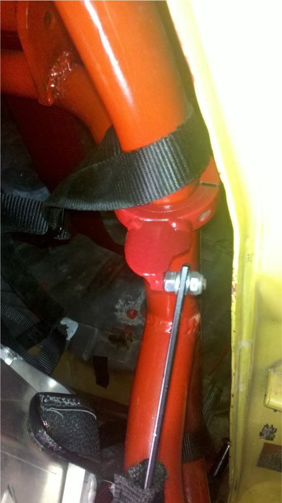
Seat Brace and shoulder strap lifter.
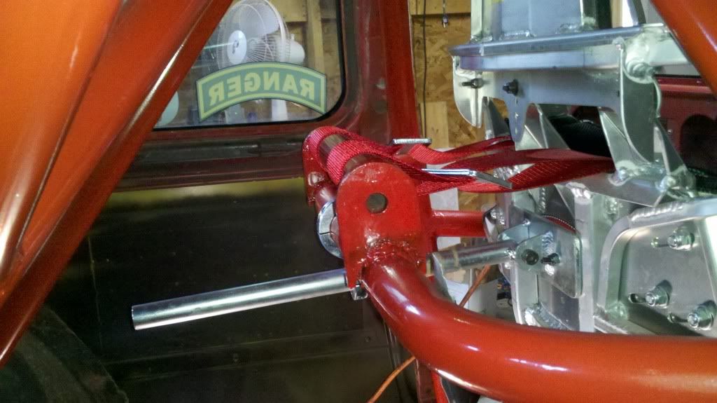
Because the seat is not FIA it requires a back brace. This pic also shows some of the reinforcing on the back of the seat and also some of the slots that make it adjustable. Note that the back brace spans two of the vertical reinforcing pieces and isn’t just a spear pointed at my back. The back brace is fastened to the back of the seats creating 6 total fastening points.
In the foreground of the pic is the shoulder strap lifter. I like my straps to go back horizontally or at least with very little downward slope. I find that if the shoulder straps go back at much of an down-angle it scrunches me down in the seat. That puts me out of position for my mirrors and the scrunching shortens the path length for the shoulder belts so they become loose. As a result every lap or so I’d have to shove on my dead pedal to push myself back into an upright position.
I originally fab’d the shoulder strap lifter for Old#6 so in order to recover it I had to cut it off of the old cage. Because of a curve in New#6’s cage I had to then shorten the strap lifter by cutting it and welding it back together.
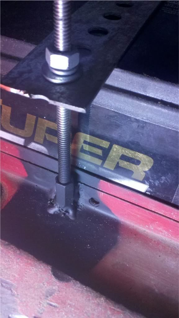
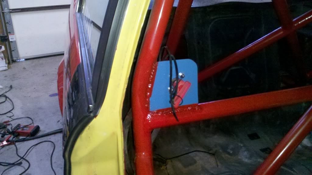
Kill switch. The plate holding the kill switch hadn’t been welded in very well. We can infer from this that someone welds even more poorly than I. While crawling around in the back seat the other week I accidently ripped the plate clean off. I was hesitant to do much grinding to remove the old welding material for fear of cutting the cage metal itself so it’s appearance really didn’t get cleaned up much. But I did reweld it back on and then paint it Infantry blue.
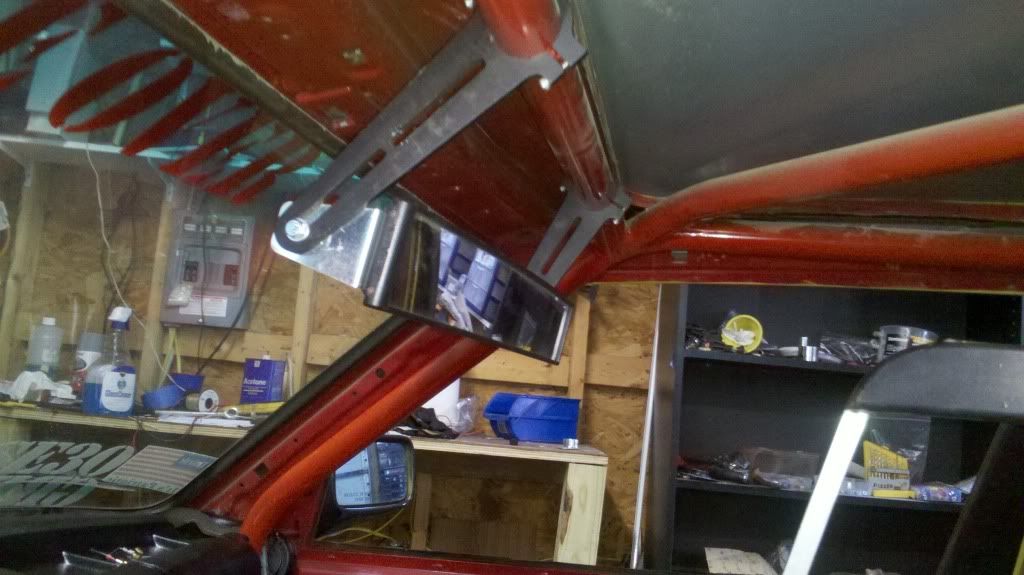
The ToDo list continues to shorten. I’m still waiting on exhaust parts and a few decals. Have to work on the alignment, imagineer a battery hold-down, and figure out how to install the rear view mirror with a cage bar that is 3" rearward of where it ought to be.
Addendum for some more detailed discussions.
Fabulous aluminum seats. I have normal shoulders and an arse of an 11yr old schoolgirl. I was determined, once I decided to get a halo seat, to find a seat that wouldn’t restrict peripheral vision, but would also hang on to my butt so I didn’t have to hang on to the steering wheel for dear life. Carbon fiber seats don’t fit me very well because either the butt is too big or the shoulders are too small. Also, if I was going to spend a bunch of money on a halo seat, I wanted it to be somewhat adjustable so I could tweak the fit over time. That seemed a lot more appealing than sending an outfit my measurements and simply hoping for the best.
I was unsure about the rib protectors. It was likely that I was going to end up buying the seat sight-unseen. Among other concerns, I didn’t know what to make of the rib protectors and worried that they would create problems for shifting and ingress/egress. Ultimately tho I ended up liking the rib protectors a lot because they significantly contribute to holding me in place. I’m not sure I entirely agree with the naming convention tho, having broken a rib slamming into my rib protector a couple months ago.
Fastening points and rigidity. With the back brace fastened to the seat there are 6 total fastening points securing the seat to the car. Also, much of the seat is 1/4" aluminum stout enough to lift the car with. In contrast there’s interesting videos out there that show how much carbon fiber seats flex both while racing and while crashing. IMO the additional rigidity of the stout aluminum seat helps the driver hear the car whisper and also helps keep the driver under control in a crash. Sure, some flex might be handy in a rearward crash, but lots of CF seats have backbraces and absorbing energy is more the role of the rear crumple zone then the seat. I think that the seat’s primary role in a crash is to maintain control of the driver. Think of it as your wife.
The below thread chronicals the purchase and installation of the seat.
http://forums.bimmerforums.com/forum/showthread.php?t=1626317&highlight=kirkey
Gauges and data loggers. The oil pressure gauge is mechanical not electrical. I fell in like with the mechanical oil pressure gauge a couple years ago when I had oil pressure and temp gauges all over the place and was irritated by the fact that they would often give me different #'s. If, for example, I’m trying to judge why my oil pressure is a couple psi lower than I think it ought to be, I want certainty that I can rely on the #'s.
The OT and CT gauges on the steering wheel cowl are Stack stepper motor gauges. It took me a couple years to finally understand the charms of high end gauges. Accuracy is not affected by imperfect grounds, they turn different colors at programmable thresholds eliminating the need for warning lights, and they have analog outs that can be relied upon. Before the Stacks I’d tried several different ways to reliably get good OT and CT into the Traqmate and none of the attempts worked very well. The TM’s 5V reference really needs to be 15-20V in order to provide decent resolution, the simple TM calibration method that should have worked, inexplicably didn’t, and the calibrations were constantly changing on me. I tried pretty darn hard to make conventional sensors work with the TM and finally gave up.
If I had it to do over again I’d have a Stack stepper oil pressure gauge instead of the mechanical gauge. Because the current gauge is mechanical it’s the one variable that I can’t log on the Traqmate. Determined to get OP logged, on Old#6 a couple years ago I had a little box squirreled away under the dash that contained an 15V regulated voltage supply. The high reference voltage pushed a lot of current thru a big power resister and it’s dedicated OP sensor. This resulted in a nice high V signal to the Traqmate and I finally had good OP data.
Discussion of the regulated power supply as the solution for feeding data to a Traqmate. http://www.spece30.com/forum/41-electrical-gauges-and-sensors/52309-calibrating-sensors-to-your-traqmate#52309 and here http://www.spece30.com/forum/41-electrical-gauges-and-sensors/54718-sensors-connection-question