


[quote=“cwbaader” post=64045]You can take the old hose connection and machine off the hose connection, drill carefully (you can’t go all the way through) and tap 1/8" pipe. That is what I ahve done several times. Or, you can use a bolt and do the same…bolt is stronger.
[/quote]
I tried to turn the 12mm hose barb into an adapter once but I couldn’t make it work. The size difference between 12mm and 1/8NPT isn’t much and it ended up too thin and fragile. I worried that as I tighted it into the block it would snap and then I’d have a helova time getting it out.
The New Ranger 6 Build Thread
Ranger
#141
cwbaader
#142
Use a 12mm bolt and only drill deep enough to thread. I have turned the threads back on the pressure switch to make them seat. cB
Ranger
#143
Gauges, tach, switches, warning lights, transponder, fan, seat, harness, and seat brace.
I got the cluster, gauge/switch panel and steering cowl gauges installed this weekend. The gauge panel on the dash has a piano hinge at it’s base so it easily flips down for access to the back of the panel. It has an Air/Fuel meter, fuel pressure gauge, and volt meter on it, and switches for fan, Coolshirt and Coolhelmet, Traqmate power, camera power.
Over the last couple of years I struggled frequently with engine management problems. The A/F meter and fuel pressure gauge were attempts to help understand what was going on. When your car hiccups on the track, the first question that pops into your mind is “fuel or ignition”. And with a fuel pressure gauge right in front of you, some of the possibilities can be excluded immediately. Anyone who’s been there will tell you that being able to reduce the number of causes with certainty is a huge step forward. Well, that is if you pay attention. As it worked out I would have figured out my problems a lot sooner if I’d not taken a year to start believing what the A/F was trying to tell me. Such are the lessons one must learn when they’ve gotten thru life mostly on their good looks.
Both the A/F meter and FP gauge have analog outs that feed to the Traqmate. Or used to, and will again once I get around to installing the TM.
The switch panel has dual grounds going to different locations. Another lesson learned is that high quality grounds make everything happier.
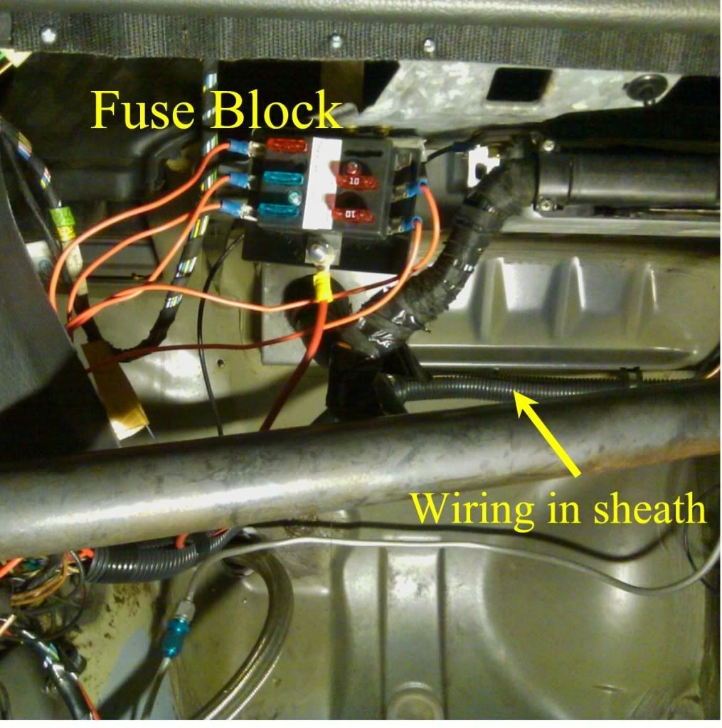
Behind the scenes there’s a 6 position fuse block going to switched 12V so most everything has it’s own fuse. The alternative would be a bunch of inline fuses but that’s a kludge. Here’s a pic of the fuse box from Old#6.
The steering wheel cowl pieces, which includes the mounts for the oil temp, pressure, and coolant temp gauges got installed once I came up with an alternative to the long 5mm screws that the cowl really wanted. I like having the critical gauges right in front of me instead of off to the side because the eyes need to divert less to scan them. Nothing like being on engine 11 to appreciate gauges. If you want to hear more about stepper motor gauges, mechanical guages, and getting data on a Traqmate Data logger read the “Addendum” after the pics. 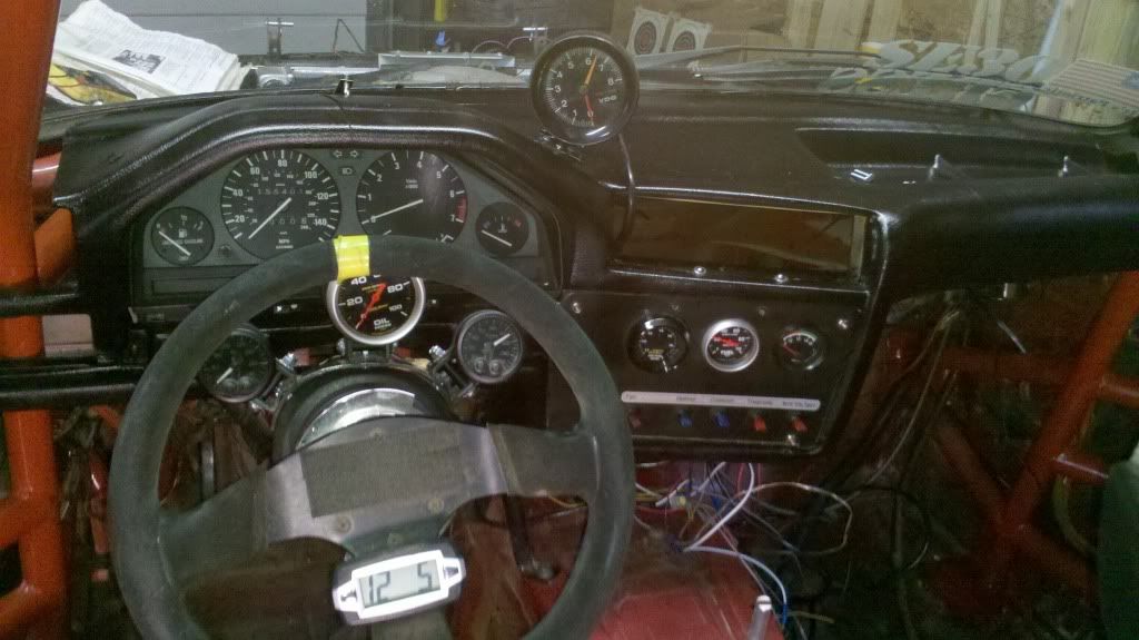
Installing the tach proved to be a little tricky. I should have mounted the tach’s base before I installed the dash. Once I got the dash in tho, I was unwilling to pull the SOB back out without out a helova good reason. I had hoped that screws would be able to get enough purchase in the dash to hold the tach firm, but it turns out there’s a layer of steel in the dash so the screws went in a bit and then just stopped.
There was no way I was going to get a drill in there to get thru the steel because there wasn’t room under the windshield. I decided that this was fate telling me that it was finally time to get one of those 90deg close quarters drills. After a trip to Harbor Freight, the tach went in nicely.
For oil pressure and coolant pressure warning lights I have a bank of LEDs on each side of the dash. Red for oil and amber for coolant. When I was playing with warning lights a couple years ago I found that no matter where I put the warning light I could not rely on instantly seeing it. That motivated me to put warning lights on both sides of the dash so no matter which way I was looking I’d immediately spot loss of pressure.
Most folks don’t have a coolant pressure switch and that’s a mistake. A coolant temp gauge will generally not warn you about a loss of coolant because the first thing that happens with a coolant leak is the coolant drops away from the coolant temp sensor. That makes it an air temp sensor.
When I first set up these warning lights a couple years ago I bought a bunch of different kinds of lights from Radio Shack and ebay. After experimenting with them all to compare brightness and field of view I settled on the banks of LEDs in the pic. They are so bright that if I start the car in darkness I have to close my eyes so the warning lights don’t burn out my retinas.
Here’s a pic of the warning lights from old#6. 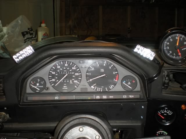
My old transponder went in w/o drama to switched 12V. Even I can’t screw that up.
The saga of the fan and switch. The PO had started the install of a SPA fan so the relay had been in place and a wire run to his old dash. But when I connected the wire that he’d set up for his old dash to my switch, the switch illuminated…WTF?. That shouldn’t have happened. Maybe there was 12V on the wire coming from the fan’s relay, or maybe the pins on that switch were not what I thought. The fan relay had a little diagram on it, but it wasn’t legible with any certainty w/o a microscope. So I spent 15min with jumper wires and a multimeter playing with the relay to figure out exactly how it behaved. Interestingly enough, the relay’s secondary (to the fan) behaves exactly the same no matter if you reverse 12V and ground on the relay’s primary (to the switch). Therefore there’s no such thing as wiring the relay’s switch backwards.
Then I did the same sort of jumper and multimeter thing with the fan switch (and it’s unlabeled pins) to ensure it really did use a pin-out like it’s buddies. You know, the other switches that have LABELs on them. I was extra cautious about this whole fan business because I still didn’t understand why the darn switch had illuminated when I’d connected the fan lead to it. I was doing a lot of wiring and was one screw up away from infinite current burning thru something, or worse.
The beauty of using little test jumpers is that they use a very thin wire. So if your testing causes a short, the very thin wire disappears in a snap of smoke and no harm done.
Finally, the secondary on the fan relay had been wired to the coil’s negative lead as a ground. I didn’t look it up but that didn’t seem right. If some tach’s connect to the coil’s negative lead, I figured that there’s no way the coil’s neg lead can be a ground. So I fastened the relay’s ground wire to the coil’s mount instead.
Seat and harness. About halfway thru all of the wiring necessary for everything above, I was struck by a desire to make the car “look” almost finished by getting the seat and harness in. The seat is a fabulous aluminum Kirkey that was bought after much research and hand-wringing. What’s terrific about it is that one can see thru the halo wings, the halo is adjustable, the shoulder pieces are adjustable in 3 axes, the rib protectors help hold you tightly in place, it can be bought in many widths, and because the cover is designed to come off, it’s very easy to add foam to the seat to make it fit even tighter. If you want to read more about fabulous aluminum seats, read the “Addendum” after the pics.
The Schroth Profi-2 harness is, of course, new. I like Schroth harnesses because their end buckles aren’t sewn in. This makes them very adjustable. With the first couple of harnesses that I had, the waist adjusters were always right in the seat holes and therefore difficult to get to. Because you can move the straps thru the end buckles of a Schroth harness, you can put the adjusters pretty much anywhere you want. The harness is also convertable for pull up vs. pull down. Skinny guys like me often like pull up, which you don’t often see in other belt systems. Since it’s convertable, you can experiment and decide which you like.

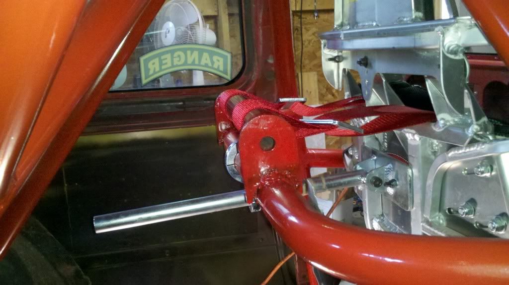
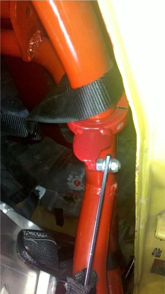
Seat Brace and shoulder strap lifter.
Because the seat is not FIA it requires a back brace. This pic also shows some of the reinforcing on the back of the seat and also some of the slots that make it adjustable. Note that the back brace spans two of the vertical reinforcing pieces and isn’t just a spear pointed at my back. The back brace is fastened to the back of the seats creating 6 total fastening points.
In the foreground of the pic is the shoulder strap lifter. I like my straps to go back horizontally or at least with very little downward slope. I find that if the shoulder straps go back at much of an down-angle it scrunches me down in the seat. That puts me out of position for my mirrors and the scrunching shortens the path length for the shoulder belts so they become loose. As a result every lap or so I’d have to shove on my dead pedal to push myself back into an upright position.
I originally fab’d the shoulder strap lifter for Old#6 so in order to recover it I had to cut it off of the old cage. Because of a curve in New#6’s cage I had to then shorten the strap lifter by cutting it and welding it back together.
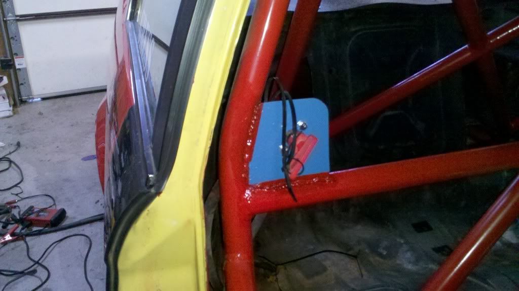
Kill switch. The plate holding the kill switch hadn’t been welded in very well. We can infer from this that someone welds even more poorly than I. While crawling around in the back seat the other week I accidently ripped the plate clean off. I was hesitant to do much grinding to remove the old welding material for fear of cutting the cage metal itself so it’s appearance really didn’t get cleaned up much. But I did reweld it back on and then paint it Infantry blue.
The ToDo list continues to shorten. I’m still waiting on exhaust parts and a few decals. Have to work on the alignment, imagineer a battery hold-down, and figure out how to install the rear view mirror with a cage bar that is 3" rearward of where it ought to be.
Addendum for some more detailed discussions.
Fabulous aluminum seats. I have normal shoulders and an arse of an 11yr old schoolgirl. I was determined, once I decided to get a halo seat, to find a seat that wouldn’t restrict peripheral vision, but would also hang on to my butt so I didn’t have to hang on to the steering wheel for dear life. Carbon fiber seats don’t fit me very well because either the butt is too big or the shoulders are too small. Also, if I was going to spend a bunch of money on a halo seat, I wanted it to be somewhat adjustable so I could tweak the fit over time. That seemed a lot more appealing than sending an outfit my measurements and simply hoping for the best.
I was unsure about the rib protectors. It was likely that I was going to end up buying the seat sight-unseen. Among other concerns, I didn’t know what to make of the rib protectors and worried that they would create problems for shifting and ingress/egress. Ultimately tho I ended up liking the rib protectors a lot because they significantly contribute to holding me in place. I’m not sure I entirely agree with the naming convention tho, having broken a rib slamming into my rib protector a couple months ago.
Fastening points and rigidity. With the back brace fastened to the seat there are 6 total fastening points securing the seat to the car. Also, much of the seat is 1/4" aluminum stout enough to lift the car with. In contrast there’s interesting videos out there that show how much carbon fiber seats flex both while racing and while crashing. IMO the additional rigidity of the stout aluminum seat helps the driver hear the car whisper and also helps keep the driver under control in a crash. Sure, some flex might be handy in a rearward crash, but lots of CF seats have backbraces and absorbing energy is more the role of the rear crumple zone then the seat. I think that the seat’s primary role in a crash is to maintain control of the driver. Think of it as your wife.
The below thread chronicals the purchase and installation of the seat.
http://forums.bimmerforums.com/forum/showthread.php?t=1626317&highlight=kirkey
Gauges and data loggers. The oil pressure gauge is mechanical not electrical. I fell in like with the mechanical oil pressure gauge a couple years ago when I had oil pressure and temp gauges all over the place and was irritated by the fact that they would often give me different #'s. If, for example, I’m trying to judge why my oil pressure is a couple psi lower than I think it ought to be, I want certainty that I can rely on the #'s.
The OT and CT gauges on the steering wheel cowl are Stack stepper motor gauges. It took me a couple years to finally understand the charms of high end gauges. Accuracy is not affected by imperfect grounds, they turn different colors at programmable thresholds eliminating the need for warning lights, and they have analog outs that can be relied upon. Before the Stacks I’d tried several different ways to reliably get good OT and CT into the Traqmate and none of the attempts worked very well. The TM’s 5V reference really needs to be 15-20V in order to provide decent resolution, the simple TM calibration method that should have worked, inexplicably didn’t, and the calibrations were constantly changing on me. I tried pretty darn hard to make conventional sensors work with the TM and finally gave up.
If I had it to do over again I’d have a Stack stepper oil pressure gauge instead of the mechanical gauge. Because the current gauge is mechanical it’s the one variable that I can’t log on the Traqmate. Determined to get OP logged, on Old#6 a couple years ago I had a little box squirreled away under the dash that contained an 15V regulated voltage supply. The high reference voltage pushed a lot of current thru a big power resister and it’s dedicated OP sensor. This resulted in a nice high V signal to the Traqmate and I finally had good OP data.
Discussion of the regulated power supply as the solution for feeding data to a Traqmate. http://www.spece30.com/forum/41-electrical-gauges-and-sensors/52309-calibrating-sensors-to-your-traqmate#52309 and here http://www.spece30.com/forum/41-electrical-gauges-and-sensors/54718-sensors-connection-question
ilateapex
#144
“The ToDo list continues to shorten. I’m still waiting on exhaust parts and a few decals. Have to work on the alignment, imagineer a battery hold-down, and figure out how to install the rear view mirror with a cage bar that is 3” rearward of where it ought to be."
The mirror is easy. With a welder in hand you should find that exhaust clamps are your friend. I used two exhaust clamps of the appropriate size for my cage and welded a 2" X 3" piece of steel to the “saddle” part of the clamp. I then added another similar sized piece of steel turned at a 90* from the first. Make two of these, one for each side. You put the clamps on the cage and the bracket goes forward towards the windshield and then turns down. My Longacre mirror is bolted to the two down hanging pieces. Make the steel pieces what ever length you need for your application. I can take a picture this evening if you would like.
Exhaust clamps are great for all kinds of cage attachments. Helmet hooks, harness keepers, etc.
Ranger
#145
[quote=“ilateapex” post=64122]“The ToDo list continues to shorten. I’m still waiting on exhaust parts and a few decals. Have to work on the alignment, imagineer a battery hold-down, and figure out how to install the rear view mirror with a cage bar that is 3” rearward of where it ought to be."
The mirror is easy. With a welder in hand you should find that exhaust clamps are your friend. I used two exhaust clamps of the appropriate size for my cage and welded a 2" X 3" piece of steel to the “saddle” part of the clamp. I then added another similar sized piece of steel turned at a 90* from the first. Make two of these, one for each side. You put the clamps on the cage and the bracket goes forward towards the windshield and then turns down. My Longacre mirror is bolted to the two down hanging pieces. Make the steel pieces what ever length you need for your application. I can take a picture this evening if you would like.
Exhaust clamps are great for all kinds of cage attachments. Helmet hooks, harness keepers, etc.[/quote]
Pls do take a pic, that sounds interesting.
juliancates
#146
They make a trick part for that:
http://miatacage.com/products/52-rearview-mirror-extension-mounts.aspx
I had to pick one of these up for the Miata because, well, everything’s too close in a Miata. I’ll be moving it over to the SE30 sometime this week.
Ranger
#147
[quote=“juliancates” post=64128]They make a trick part for that:
http://miatacage.com/products/52-rearview-mirror-extension-mounts.aspx
I had to pick one of these up for the Miata because, well, everything’s too close in a Miata. I’ll be moving it over to the SE30 sometime this week.[/quote]Ah, now that’s not a bad trick. If I can’t pull a rabbit out of my own hat, I may either buy that of fab something similar.
cwbaader
#150
NOTE…The closer the mirror is to your face, the more field of vision you have from it. Think on that. CB
Ranger
#151
Mirror solution. I went to the parts bin and looked thru all the hardware I have that is designed to attach to a cage. And I found some long clamp-thingees.
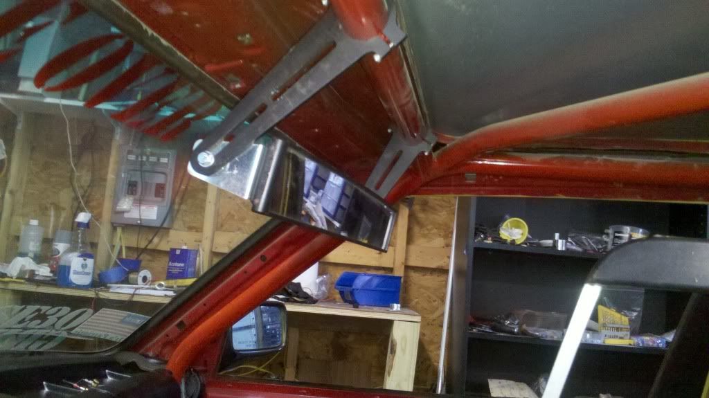
Re. Mirror being close and range of view. Sure, a close mirror gives more field of view but my eyes aren’t what they used to be and they don’t change to close focus very well anymore. The closer the mirror is the closer your eye’s focus has to be.
Plug for Allview. If you have a panel mirror or a panaramic mirror, then my mirror is a helova lot better than yours. No misaligned panels and very little panaramic distortion. A better mirror might keep you out of a wall one day. Wait, ah, that tag line was not ideal. Call Marketing and ask them WTF they’re thinking.
cwbaader
#152
Scott, you don’t focus on the mirror…you focus on what is reflected in the mirror, and a panoramic mirror works best. CB
Ranger
#153
A person would think so, but put a small mirros 1" from your eye such that it takes in the scene behind you. See how hard it is to snap your vision from infinite front to the mirror.
Ranger
#154
Engine won’t start and the exhaust is all messed up.
The car won’t start.
I needed to move the race car out of the garage so I could bring in the new e46 DD. This would get New#6 off of the scissor list so I could try to fit the exhaust, and it would let me work on the e46 at night. But all the sudden I couldn’t get the race car to “catch”. The starter was turning the engine but it wasn’t firing. There was a schedule here that needed to be adhered to. I needed the darn car out of the garage and with quiet hours starting at 9PM and the car with no exhaust, I had only about 30min of available time to get the car started and moved. Otherwise I was hosed and the evening’s planned work was going to slip a day. And that’s always a pisser.
Although I’d done a fair amount of work on the car in the preceding week, I’d not touched engine management so I didn’t understand why the race car wouldn’t start. I spent some time standing over the engine bay scratching my head wondering “what did I change”? To check that I was getting fuel, I disconnected the fuel line and ran the starter. No fuel. Then I jumped the fuel pump relay and confirmed that the fuel pump was good. So I started focusing on the crank pos sensor, checking it’s gap, reseating the connector, and generally wiggling wires…when the CPS sensor wire popped right out of the CPS. “Ah hah” I exclaimed.
So I replaced the CPS from the copious spares, turned the ignition key and… the car still didn’t fire up. $@##!.
I went back and checked everything over again to see if I’d confused something. By then I was really scratching my head as to why my fuel pump wasn’t being told to pump fuel. At some point a person has ruled out all the low hanging fruit and is grasping for unlikely straws like…even tho you’re positive that you didn’t fool with the like connectors of the CPS and plugwire #6 sensor since the car last ran, you check anyways because e30 fairies might have switched them when you back was turned.
Eventually it was 1AM, I was out of ideas, so I decided to have a beer on it. Er, I mean sleep in it.
The next day at work I had a sudden epiphany. “Hey, didn’t I disconnect the DME cable because I was welding the other night”? So when I got home I took a look and sure enough. Altho in a casual inspection the cable looked attached to the DME, one tug of the connector made it clear that it was not attached after all. And so was solved the mystery of WHY THE HECK WON"T THIS DAMNED ENGINE START?!!
The silver lining is that the CPS with the weak cable got replaced before it failed on it’s own.
Exhaust.
I was concerned that the exhaust might have been bent in the crash and therefore not fit. I was hoping tho that the entire exhaust system had simply beeny moved backwards 8" or so when the engine was pushed back by the impact, and therefore had survived unscathed. If not entirely unscathed, “surely Midas can bend a tube a bit to make it work”, I figured.
The test fit of the exhaust had to be done in the driveway up on jackstands. The scissor lift is no place to try to work on an exhaust, but that meant working in the darkness by flashlight. To make things a little harder my exhaust is all welded together so there’s no separating pieces to ease the install.
After struggling for 90min with the 30lb very ungainly 14’ long beast by flashlight under the car in the inky darkness, I was done. The damned thing needed to go to Midas. I figured that they’d be able to do some cutting and bending to cobble together an exhaust system. I had tried and tried to get the beast to fit, but I could either run it under the car or I could push it up to the exhaust manifold but try as I might I could not seem to get it to do both. I was frustrated, dirty, and exhausted from wrestling with the beast half the night. The SOB was all messed up and wasn’t going to go on except in little pieces.
The failure of the exhaust test-fit meant the car had to go to Midas. Had to go on to the trailer to go to Midas. And had to have brakes to go on to the trailer to go to Midas. And that was a problem. The darn car, you see, really didn’t have much in the way of brakes. Since I had brake lines open for a week during the suspension and rear subframe replacement, a lot of air got into the system. The failure of the Speedbleeders and the two failure fountains (of brake fluid) from the pressure bleeder had left a bunch of air in the brake hydraulics.
After a logistical pause to conduct Class IX resupply (Armyspeak for having a beer), I marshalled my reserves of enthusisam and by 11PM I was replacing the failed Speedbleeders with normal bleeder valves. By flashlight of course. Just the fact that I found normal bleeder valves among the copious spares was a nice commentary on being organized. As I hit the AM I took a look at the pressure bleeder to discover if the cause of brake fluid fountain #2 might be overcome. This was a big deal because w/o the pressure bleeder I was going to need help bleeding the brakes. And that would be a problem.
I contemplated the least of 2 evils…I could get one of the kids to help me bleed the brakes and invite an agony of haplessness and frustration, or I could wheedle and badger until the wife grudgingly helped for 15min, knowing that she’d hold that against me for a year.
My wife cuts me an awful lot of slack to pursue my obsessions, but only with the understanding that I not bother her with them. With Italian heels on, climbing into a car that is up on jackstands, crawling over the cage and then down to sit on the hard dirty floor pan (no seat), and then creating perfect harmony between pedal and bleeder valve, all in inky darkness was going to take a long time to fade from recall.
After pondering the value of both my sanity and my marriage, I went and took another look at the pressure bleeder. In the first bit of real luck in several days it turned out that the 2nd brake fluid fountain had not been a product of a busted plastic nozzle on the jug, but instead inadequate Home Depot hose. Up in the attic spares dept in the “misc hose bin” I found some fuel line that looked like it would work ok and I installed it on the jug with a quick release fitting at the other end.
The next night I put a half liter of SuperBlue thru the system and dropped the car off of the jackstands. Nothing like a pressure bleeder to keep the divorce lawyer at bar. Then I fetched the trailer and, noticing that the brakes were still pretty bad, put the car on the trailer only minutes before the 9PM beginning of quiet hours, and carefully tucked 14’ exhaust pipe on the trailer beside the car perilously close to my fabulous new paint.
Also, I had a spare set of exhaust downtubes among the several e30’s that are disassembled in our attic, so the spare downtubes got loaded up too, in case Midas might need them. The wife doesn’t realize how many parts I have up in the attic because she doesn’t normally go up there. It’s only a coincidence that cracks are appearing in the master bedroom ceiling.
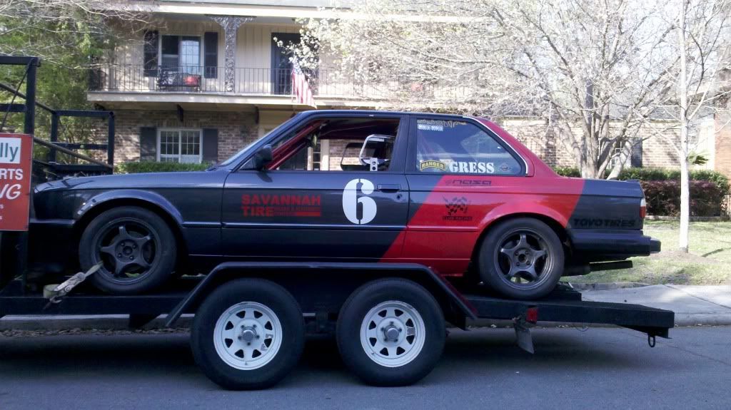
The following morning, race car, 14’ of exhaust, and the spare downtube went to Midas. And 8hrs later they were home again, The Midas Touch having no more luck than I with the bent 2-into-1 exhaust collector, I would be calling the SpecE30 exhaust guy for parts.
Altho I would not get the exhaust parts for another two weeks, the effort was ultimately successful. The pic below shows the car just back from Midas shyly wearing it’s first SpecE30 exhaust system. The flex coupling on my old downtubes was apparently cracked in the crash so another gold star for the attic based spares dept.
Ranger
#155
The “To Do” list never really gets smaller, it’s just that the things that get added to it become more and more minor. A number of tasks got complete while I waited on exhaust parts
Alignment.
I’d been kind of putting this off for fear of bad news. I’d taken a calculated risk last month when I swapped in the subframe from the crashed race car. But other then my calibrated eyeball I never really confirmed that my old subframe came out of the crash unscathed. The drive train took a helova whack when the engine was pushed back. The tranny mounts snapped, the shifter rod was shoved thru 6" of sheetmetal, and the linkage between tranny and driveshaft sheared. Therefore the diff certainly sustained a helova blow and that could easily have distorted the rear subframe.
Figuring that I might as well attack the most problematic thing first, I started in on rear toe. There’s a number of ways to DIY toe but I use a laser level and toe plates and shoot a beam from the rear wheel forward past the front hub. Because you are measuring rear toe not at the rear rim but instead at the distant front hub, this technique exaggerates any toe problem by 6x. That makes it easy to very precisely set toe. The initial check of toe found that both right and left goofed, but not critically so. The right rear had about 1mm toe out and the left had about 5mm of toe in. The goal for rear toe was just the slightest amount of toe in.
I have aluminum subframe bushings. Before I installed my old subframe on New#6 I had cut away a little of the aluminum subframe bushings such that there would be more clearance to get a wrench on the rtab adjuster bolt. Nothing like having done this a couple times before to know the tricks. But…I still couldn’t quite get a thin wrench in place. It was so incredibly close, so tantalizingly close, to “clicking in” on the adjuster nut, but it wasn’t quite there. After 20min of struggling to get the standard thin wrench on to the nut, I became more and more certain that I’d cut-down a thin wrench last year for exactly this nut. So I got up and started hunting around my tool boxes and the two garages for that customized wrench. But after having looked everywhere, found other customized wrenches, and lost some confidence that my memory was accurate, I went back to trying to turn “tantalizingly close” to “eureka”.
After another 20mins of struggle trying all sorts of things to get the nut to budge just a little so I could get the wrench on, I started wandering around the 2 garages again looking for the cut-down wrench that I could have %$*#^@!! sworn I made last year. Since it was after midnight, I couldn’t cut down another thin wrench because the grinder would be too loud with the warm weather encouraging the neighbors to open their bedroom windows.
Once again failing to find the custom thin wrench, I marshalled what tenacity remained and began a 3rd iteration of 20min trying to get to the damned adjuster nut. And got no where. Frustrated, realizing that I either found that wrench I’d made last year, ceased fire until I could make a new wrench the next day, or threw myself off of a goddamned bridge, I searched one last time for the cut-down thin wrench before I called it a night. It looked like I’d be firing up the grinder the next evening to make another wrench. Which is when I FOUND THE SOB. Right where it was supposed to be, of course, albeit cleverly hiding under the clutch alignment tool.
In a side note…Last year I had problems with the right toe of my weld-on toe/camber kit. The toe setting wouldn’t stay where I put it for love or money. It only required a couple hot laps to shift the right-rear from a smidgen of toe-in to a buttload of toe-out. Given that the whole reason I went to the weld-on toe/camber kit was so that I could create alignment that I wanted and have some confidence that it would stay there, the shifty toe problem was highly irksome.
In order to hold the toe setting in place last year I’d fabbed a device that anchored the right toe adjuster’s eccentic. But I found in the fight with the subframe on New#6 that my idea worked a lot better on Old#6. The problem was that the new car’s gas tank didn’t have the same big-arse dents in it that the old car had, providing clearance for the mod. As a result I couldn’t really grab on to my eccentric holder and set it to hang on at the new eccentric position. That is to say, now my eccentric holder, doesn’t.
Back to the main feature. Making good progress now that I had the cut-down wrench, at 1AM I finally said “screw it, it’s good enough”. 0.5mm, toe in RR, perfectly neutral LR. Only because my measurement technique magnifies toe by 6x was I able to see the negligible 0.5mm toe in. A shop’s alighnment system might not see that at all.
Window net.
Altho it took 2 days for the red paint to dry on the window net fastening device. It went in w/o drama.
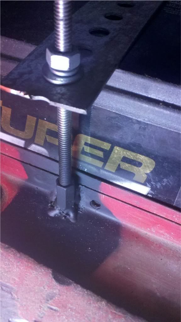
Battery hold-down.
I spent way too much time scheming and trying different battery hold down ideas. The one I finally went with uses a long nut that is used for connecting threaded bars together. I managed a couple decent tacks w/o burning thru the sheetmetal. When it comes to me welding sheetmetal, it doesn’t get better than that.
Matt_H
#156
This has got to be the best description of race car preparation that I’ve ever heard.
Thanks for letting me know that I’m not the only one who goes through these frustrations with building/maintaining a race car. You’re just better at putting it into words than most of us are.
It’s good to see the progress and I’m looking forward to seeing the new #6 out on track.
Ranger
#157
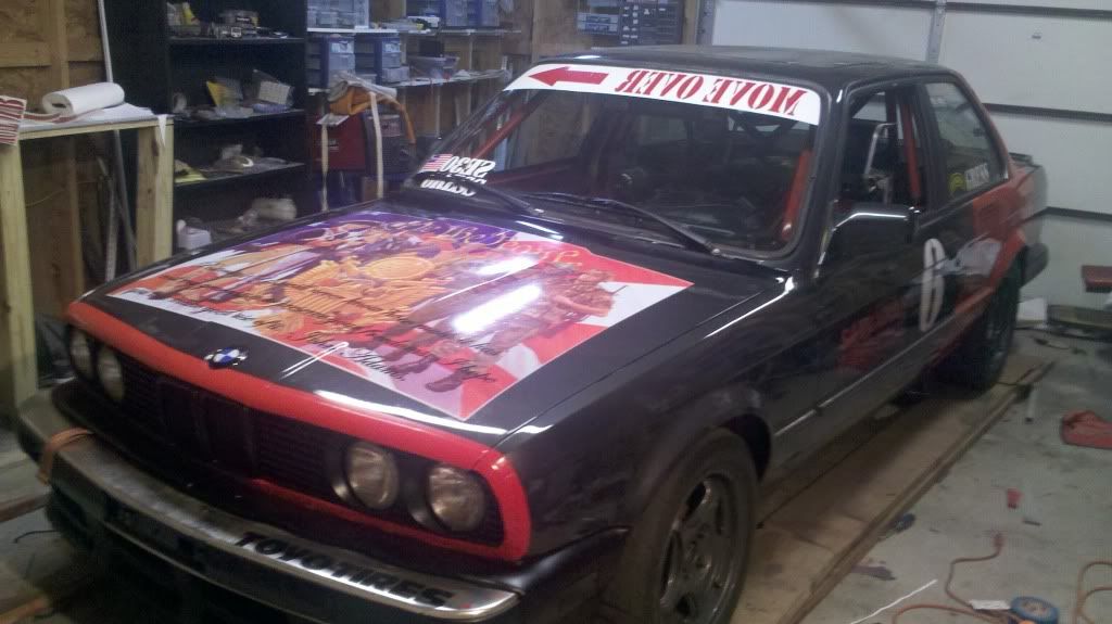
Livery almost complete. Put the big historic soldiers decal on the hood with the John Adams Quote, removed the first “Move Over ====>” decal attempt that wasn’t visible enough and put the 2nd effort on. White background and bigger letters. I also put red around the leading edge of the hood, and black on the trailing edge. This will protect the parts of the hood where the paint takes a beating.
On Friday I went by the PickNPull and found a cherry, and relatively rare, 318is to pull some parts from. Well, cherry except for the significant front and rear damage. It had been darn clean before the wreck. Got a windshield wiper arm, door handle opening mechanism, abs and CEL dash lights. Still need a front bumper reflector.
Have been scheming on fabbing a skid plate. I wish I could weld aluminum.
Somehow the car came back from Midas with a brake cooling hose ruined. Fortunately I have a bunch high temp 3" hose in the attic so replacing it wasn’t a big deal. Also wire-tied the muffler to the car as a backup to the rubber donuts.
New coolant pressure switch installed. I couldn’t seem to find the one from the crashed race car, and the one I installed from the parts bin is wrong and illuminates when there is pressure as opposed to illuminating when there’s no pressure. I think I found a far cheaper way to do this than my previous efforts. http://www.amazon.com/gp/product/B000LN6AEQ/ref=oh_o05_s00_i00_details
I couldn’t find my windshield mylar which was a real pisser. I had a big tube of the stuff that I got for beer money and normally it’s really expensive.
Would be nice to get the abs working before it’s first track day in 2 weeks.
Got this to get a 2nd opinion on my camber gauge. Really works well. http://www.amazon.com/gp/product/B001PTGBRQ/ref=oh_o04_s00_i00_details
turbo329is
#158
When I was talking about buying a really unprecise digital level I was talking about one of those. Cancel the order or send it back. It is junk.
I think this is the one we had in the Army for adjusting Apache tail rotors. Notice the price difference. You get what you pay for except that the Army pays over 600 for it.
http://www.amazon.com/Macklanburg-PRO-3600-Digital-Protractor/dp/B00481QCYA/ref=pd_sim_sbs_indust_3
Ranger
#159
New#6’s first day at the track was today at Roebling. Nothing fell off. The biggest problem was I was blowing a lot of blue smoke and going thru oil like crazy. I’m hoping that the two are related. I found that oil is leaking out of the rocker arm cover worse than I’ve ever seen. Tightening it down didn’t seem to help. I took the rocker arm cover off and a check against a level ID’d the fact that the rocker arm cover wasn’t very flat. I figure also that the rocker arm cover gasket is probably old and dry, and therefore couldn’t handle that ~1mm “non-flatness”.
I found 5 rocker arm covers in the attic so I grabbed the flattest one and a new gasket and will put that on in the morning.
I’m hoping that the cause of the blue smoke is oil dripping off of the engine on to the exhaust farther back. There’s no air pulses coming out of rocker vent hose so there’s no way the rings are leaking. Could be a bad valve seal tho.
I corner weighed the car and I’m off by 31 lbs. That’s not that great. I’m going to try to get that <10lbs.
The shifter has a really long-ass throw.
jlevie
#160
Woo, Hoo! That is what we’ve been waiting to hear. It sounds like the car doesn’t have any major problems and what problems it has will be easy to fix.